Enabling worksharing involves creating a master project model, known as a central model, from an existing model.
The central model stores the current ownership information for all worksets and elements in the project, and acts as the distribution point for all changes made to the model. All users should save their own local copy of the central model, edit locally in this workspace, and then synchronize with central to publish changes to the central model so that other users can see their work.
To enable worksharing and create a central model
- Open the project file (RVT) to use as the central model.
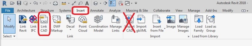
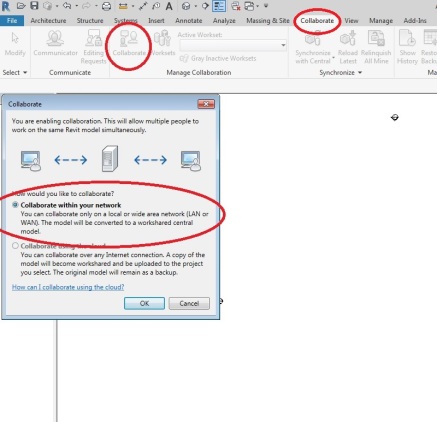
- Click Collaborate tab
 Manage Collaboration panel
 (Worksets).
The Worksharing dialog displays, showing the default user-created worksets (Shared Levels and Grids, and Workset1).
- If desired, rename the worksets.
- In the Worksharing dialog, click OK.
The Worksets dialog displays.
- In the Worksets dialog, click OK.
You do not need to create worksets at this point.
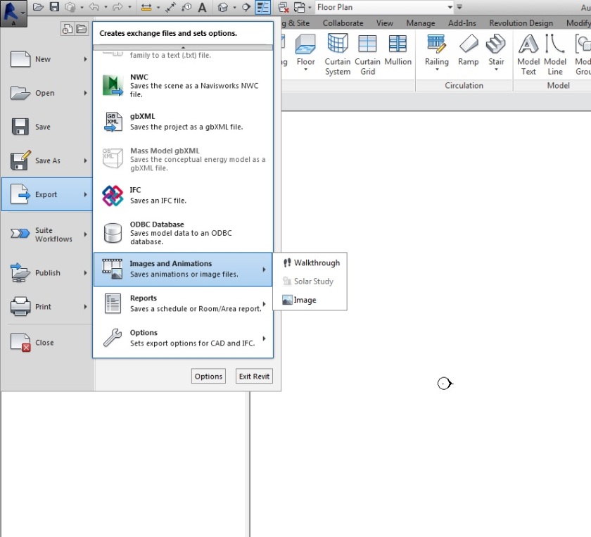
- Click File tab Save As
 (Project).
- In the Save As dialog, specify a file name and directory location for the central model.
When specifying a name for the central model, use a naming convention that identifies it as the central model (for example, OfficeBuilding_CentralModel.rvt).
- In the Save As dialog, click Options.
- In the File Save Options dialog, select Make this a Central Model after save.
Note: If this is the first time you have saved after enabling worksharing, this option is selected by default and cannot be changed.
- Click OK.
- In the Save As dialog, click Save.
-
The file is now the central model for the project. Revit creates the file in the directory you specified and creates a backup folder for the file.

 Collaborate.